Booth's Sequential Multiplier Simulator, version 1.0
Booth's Sequential Multiplier Simulator, version 1.0
Booth's Sequential Multiplier Simulator, version 1.0
Booth's Sequential Multiplier Simulator user guide, version 1.0
User guide.Release notes.
The "BSMS" has five main areas:
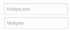
- Input area:
|
It has two input fields, "Multiplicand" and "Multiplier". The input type of those two fields must be binary(a maximum of four characters [0-1] are only allowed). In case of error a note with some suggestions for the correction will be shown. |
- Change Language
|
It has four links ("It", "Eng", "Help-Info", "Home"). The first, "It", allow the user to change the language of the page to italian. The second, "Eng", allow the user to change the language of the page to english. The third, "Help-Info", it's a link to this page , where the user can read more information about this program. The fourth, "Home", it's a link to the main page of the project's site. |
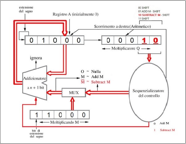
- Circuit area:
|
It has the BSMS's graphic circuit representation. The following are the main components: M Register, it has the "Multiplicand" input field data(described in the previous section), Q Register, it has the "Multiplier" input field data(described in the previous section), A Register, initialized to "00000" will contain, step by step, the result of sums (or subtractions) with M register. Sequentializer Control cecks Q register's last two bits and determines the operation to be performed, The MUX receives ,bit for bit, the values of M register's values ,and two bits from Sequentializer Control , as control bit, to select the exit line: n+1 bit Adder : examines the bit sended by the Sequentializer Control : |
- Functions area:
|
It has three buttons ("Start", "Next", "Reset"): "Start" button to start a new operation. "Next" button, through which it is possible to advance in the program's instructions. "Reset" button, through which reset everything. |
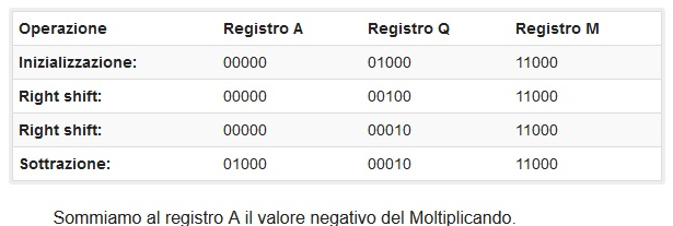
- Operation area:
|
Each row of the table will contain the executed operation and the values of the registers after this step. When all steps are done, a message will be shown to advise the user of the completion of the operation. |
![]()
![]()
![]()
Dat: 28 July 2014
Simulator of Architettura degli elaboratori (2013-2014, U. Catania, DMI)