The BCD to seven segments code decoder simulator is a web-application that allows to simulate the said circuit, introduced in the appendix A of the book Computer Organization, by C. Hamacher, third edition.
Due to its nature, it is possible to start the simulator directly online, or download it and start it offline. For furher informations check the file Installation notes.
The program user interface is made up of three sections:
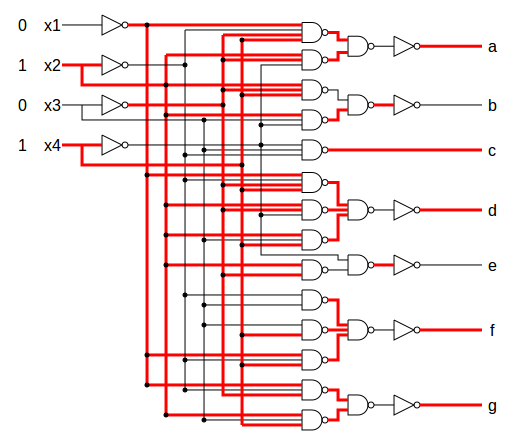
The represented circuit is a set of NAND and NOT logic ports, in addition to links, inputs and outputs.
It implements the decoder subject of the simulator.
On the left, labeled from "x1" to "x4", there are the fuor inputs controllable from the input panel, with the actual simulated values on their side.
Along all the circuit, input signals travel in the two states "0" and "1" that are represented like this:
After going through the circuit, signals reach the different exits, on the right of the circuit, labeled from "a" to "g", that represent the segments of the output display, that will be on or off, depending on which the exit is 1 or 0.
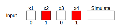
The input panel is made up of 5 buttons:
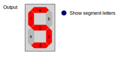
The output display shows the result represented by the circuit.
It is made up of 7 segments labeled with the letters from "a" to "g", that match the outputs of the circuit. The segments can be grey or red, depending on which the matching exit is 1 or 0.
There is also a button that allows to show or hide the letters of the different segments.